This page contains the current status of the robot I’m building for the ServoCity balancing robot contest. My robot’s name is Red. He was named on September 25, 2014. The most recent entries are at the botttom.
September 13, 2014 – Today, I started working on the design for my entry into the ServoCity balancing robot contest. I’ve built balancing robots before, and the Actobotics kit is the best available for building robots, in my opinion, so how difficult can this be? 😉 The contest requires that everyone use a 24 inch piece of tubing or channel. I plan to use this channel as the vertical backbone of the robot. A smaller horizontal channel will attach at the bottom of the backbone. On this channel will mount the wheels. The primary mechanical challenge is finding a way to mount the wheels to the channel. I can think of four methods:
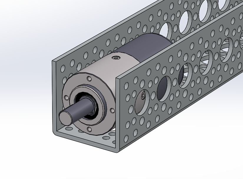
- Mount the motor inside the channel, as shown in the following drawing:
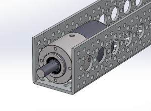
This seems like the best method because the motor is protected. ServoCity sells a small planetary gearhead motor that would fit in the channel. However, there is currently no way to attach the motor to the inside of a channel, and the motor does not have an encoder. For these two reasons, I will need to try another method. - Mount the motor on top of the channel, as shown in the following image on the ServoCity website:
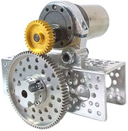
The problem with this method is objects can get caught in the point where the two gears mesh. I know from previous experience that balancing robots can get a bit “wild” in their movements, particularly during initial testing. I can envision fingers getting crunched in the exposed gears. If I had time, I could fashion a cover for the gears, but the robot needs to be done in a month, so for now I need another method of mounting the motor. - Mount the motor to a vertical piece of channel, as shown in the following drawing:
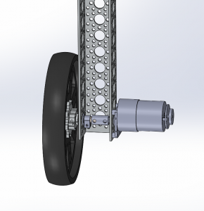
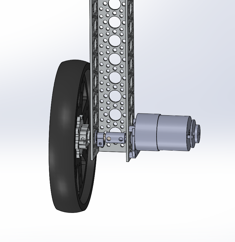
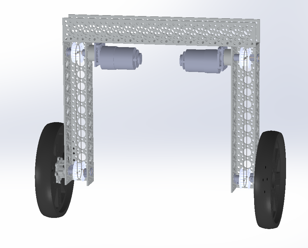
Adapters are available to mount a gearhead motor such as the Pololu 37D motor. In this configuration, the wheel is supported by a bearing, which is good because the 37D motor has only a bushing. However, the big problem with this arrangement is that the motor is too exposed. It would be easy for the motor to hit an object and become damaged. - Mount the motor high up and connect it to the wheel using a pulley and belt, as shown in the following drawing:

The disadvantage of this method is that it is more complicated than the direct drive method just described. However, the motor is protected, and the wheel is supported by two bearings, which is great.
After weighing the pros and cons of each method, I have choosen method #4. Another major design decision is what microcontroller (MCU) to use. I would love to use a cheap $15 STM32 developement board, but the contest requires that all electronics be purchased from ServoCity, Pololu, or SparkFun. SparkFun sells a Cortex M board that is designed to work with mbed. That’s tempting, but because of the desire to make a kit for the masses, I’m going to try an Arduino. I found a product called the Netduino Plus 2 on SparkFun. It even uses an STM32, so if I run into a limitation in the Arduino IDE, I can always program it directly using a J-Link and Keil.
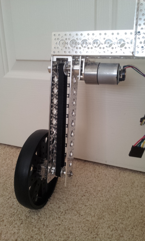
September 24, 2014 – I showed my robot at the Homebrew Robotics meeting tonight. I also mentioned the ServoCity contest. Someone asked what the prize was and how much money I will spend. I explained that the prize was $1000 worth of parts, and I will probably spend close to $500. Thus, to make this a financially profitable venture, my odds of winning would need to be greater than 1 in 2! Video from the meeting is posted on the Homebrew Robotics YouTube channel. I’m the guy in the gray shirt. Here is the robot in its current state:

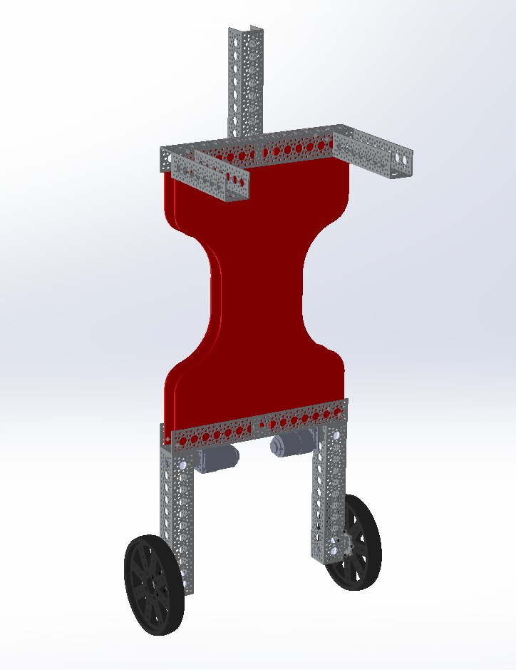
September 25, 2014 – I figured out how I’m going to attached the electronics and at the same time give my robot a more natural contour: I will cut out an hour glass shape out of acrylic and attach it between the upper and lower aluminum channels, as shown in the following drawing: The curvy shape gives the robot a more organic appearance which helps to offset the industrial feel of the aluminium. The acrylic will be red. The color red is a bold color that stands out in a crowd, and it implies that the robot has life in it because blood is red. The color also give my robot a simple name: Red.
September 26, 2014 – I tried to use the NetDuino Plus 2 that I bought from SparkFun and had hoped to use as the controller for Red. I discovered that it is not really an Arduino, and it does not work with the Arduino IDE. It requires Visual Studio Express. Ugghh. I’ve have some basic experience with the Arduino IDE, and I use Keil every day. I don’t have time to install and learn another IDE in time for this contest, so I need another controller board. One of the goals of this contest is to create a kit. An Arduino is a good choice for a kit because Arduinos are so ubiquitous. A kit that required someone to lean Keil probably wouldn’t sell as well to the general maker community. The Arduino Due looks promising because it is fast and has a lot of inputs and outputs, so I will try one of those.
Sunday, October 12, 2014 – Today I went to the office and 3D printed “mittens” to represent hands and a “neck” to hold the phone at the top of the robot. I also laser cut the body panels. The back panel has holes in it to mount the electronics. I discovered the the 3D model I downloaded for an Arduino Mega, which has the same hole pattern as the Due that I am using, had a mistake in the positioning of the holes! Fortunately, I cut the first panel out of paper. I found the problem when I dry fit all of the electronics on the paper panel. The lesson learned is to double check critical sizing elements of models that I don’t create myself. All of the electronics and mechanics were finished today. Tomorrow I will try to finish the software before the deadline, but it’s looking doubtful that I will finish on time. Here is a picture of Red without his front panel:
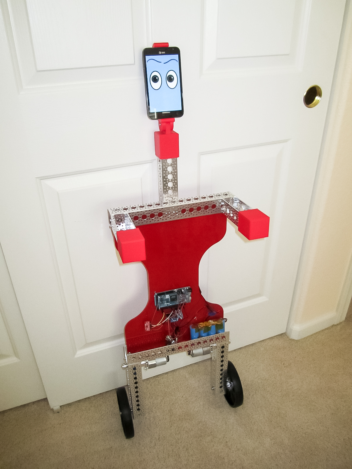
The eyes are an Android app from the Oddwerx project. Oddwerx was originally a prototype for a commercial product. It is now an open source project.
Monday, October 13, 2014 – The deadline for submitting a video of the robot balancing has been extended two weeks to October 27! I have a chance now of completing the software on time.
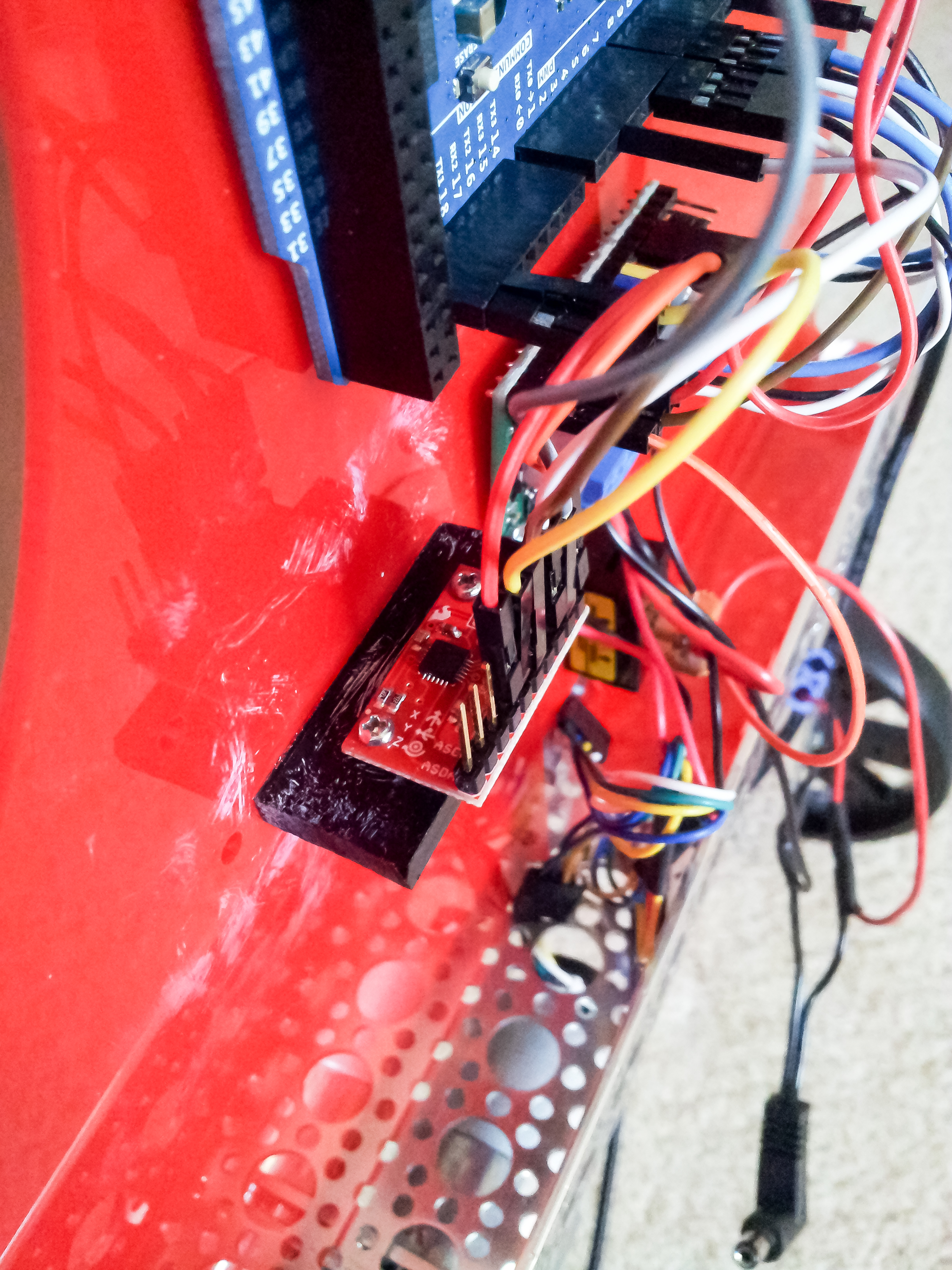
Tuesday, October 14, 2014 – I discovered today that the MPU-6050 does not give accurate readings when mounted vertically. I believe that I am running into the gimbal lock problem. When I tested the MPU-6050 on my desk, it was lying horizontally. I should thought to test it in the position that it would be installed in the robot. To fix the problem, I attached the MPU-6050 to a small piece of acrylic which I glued to the back panel in a horizontal position:
Thursday, October 16, 2014 – Red’s motors moved for the first time today on the mechanically and electronically complete frame. I consider this step to be the birthday of my robots.
Saturday, October 18, 2014 – I was going to port code for a PID control loop from a previous project to the skectch for RED, but then I found an awesome open source PID library for the Arduino. The author, Brett Beauregard, does a great job of explaining how the library work on his website. With mininal additional work, I was able to make RED move like a Segway. When RED tilts forward, the wheels move forward. When he tilts back, the wheels move back. The more he tilts, the faster the wheels move. This is “proportional gain” portion of the PID control loop. RED is not able to balance on his own at this point. A human is required for balance. To make RED balance and achieve full PID control, I will need to add Integral and Derivative gain.
Monday, October 20, 2014 – PID tuning is turning out to be a major pain. The only way I have to change the PID parameters is to edit the sketch and recompile. This process takes me about a minute on the Arduino Due. I’m tempted to create a separate box with rotary dials that could plug into the Arduino so that I can input new PID parameters.
Tuesday, October 21, 2014 – I decided that I don’t have time to implement my “PID box.” I will make it a separate project after RED is complete because I’m sure that I’ll be making more balancing robots.
After a bit of PID tuning, RED is now able to balance on his own! He is still a bit wobbly, but, nonetheless, this is a major milestone.
Friday, October 24, 2014 – I spent two days just tuning the PID loop. I have finally achieved a stable balance. Now on to the video that I need to submit for the contest!
Sunday, October 26, 2014 – Friday afternoon and part of Saturday I shot video of RED operating in various situations, including being used as a telepresence robot. After two days of video editing, I have a video that I can submit for the contest. I’m actually done a day before the deadline!
You can watch the video here:
The results of the contest will be announced on Friday. It will be interesting to see what other people came up with.
Really great work congratulation. Am a mechatronic student and i work in project like it .can you help me ? by supply me more information about red and thanks for this wonderful project . go away the sky is limit ….
great robot, where is the instructions?